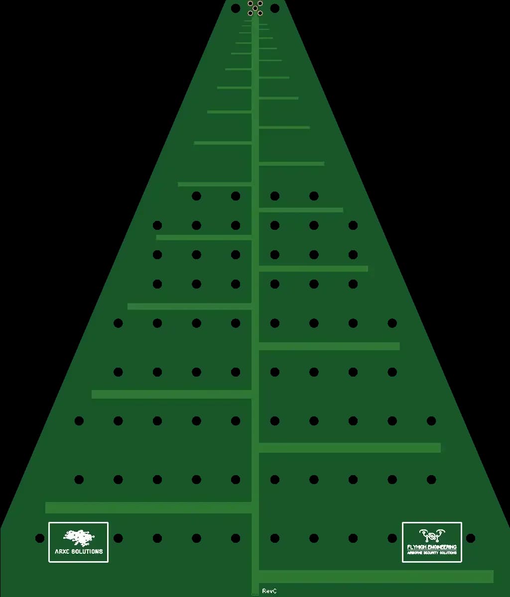
Log-periodic antenna 530–6000 MHz — radiation pattern
Anechoic-chamber radiation-pattern measurement of the 530–6000 MHz log-periodic antenna. The compact model in the range: a 305 × 260 mm board with a 530 MHz lower edge. The 2D and 3D plots are interactive — rotate and zoom them straight in the browser.
This page carries the measurement of the ARXE 530–6000 MHz log-periodic antenna, the compact model in the range. A 305 × 260 mm board working from 530 MHz to 6 GHz. The lower edge is set by the longest element of the structure — about 283 mm, half a wavelength at 530 MHz.
The measurement shows how that geometry holds the shape of the pattern across the whole band: from the bottom edge, where the longest elements on the board do the work, up to 6 GHz, radiated by the shortest part of the structure. For a log-periodic antenna that is the real question — not absolute gain at one point, but how steadily it keeps its direction as the frequency crosses the band.
What to look for: compare the width of the main lobe at the bottom and top edges, and watch the level of the back lobes. They decide how well the antenna ignores a transmitter shining into its back — in dense urban spectrum that often matters more than a few decibels of gain.
This is the smaller antenna of the pair. The same measurement for the larger model, which works from 300 MHz, has its own report: the difference in board size shows most clearly in the plots at the bottom of the band.
Both plots are interactive: the 2D pattern opens full screen, and the 3D one rotates and zooms straight in the browser, with no separate software.